Company dynamics
2026-09-30
How to Match Extrusion Press Tonnage to Large Aluminum Profiles
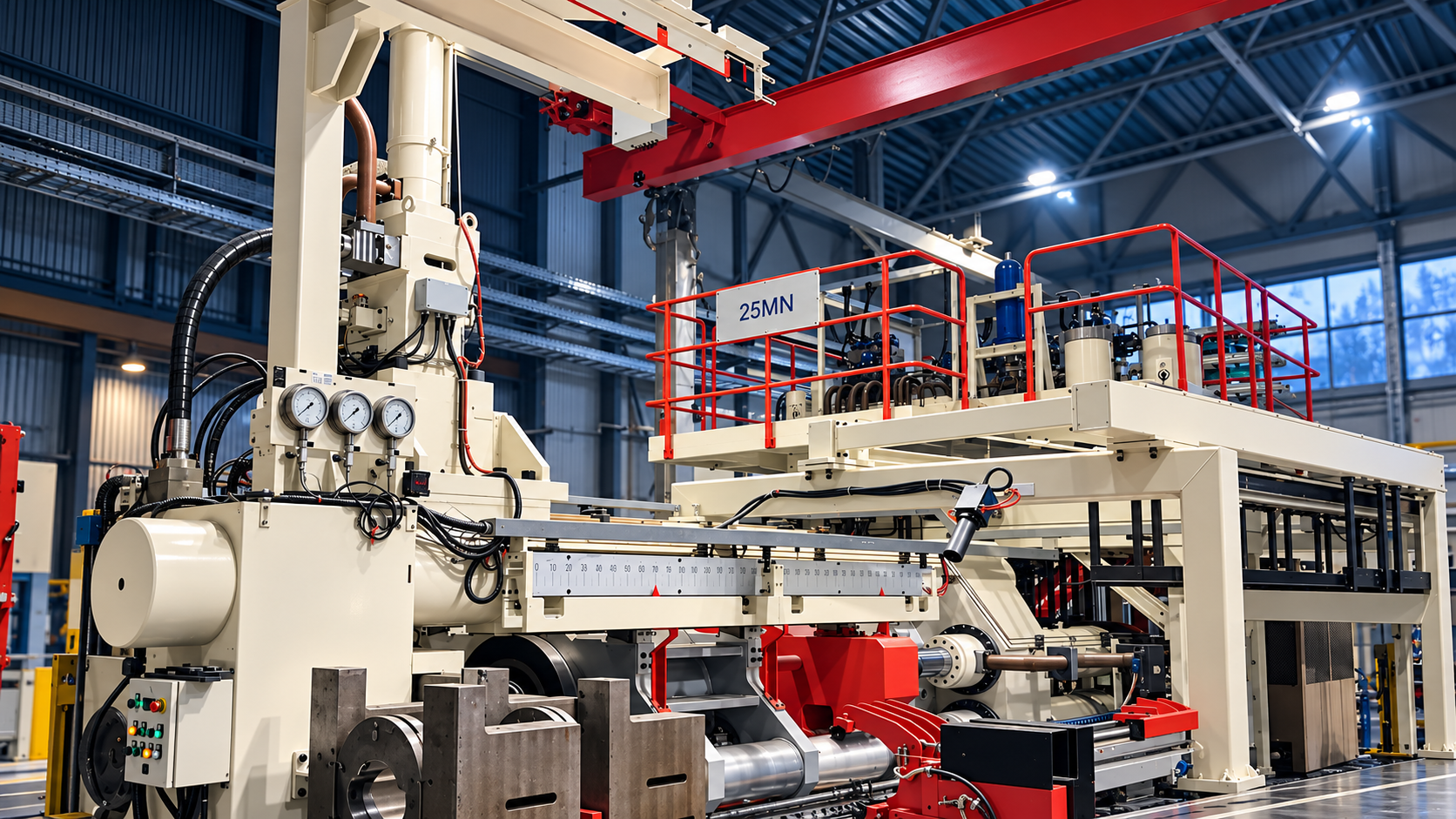
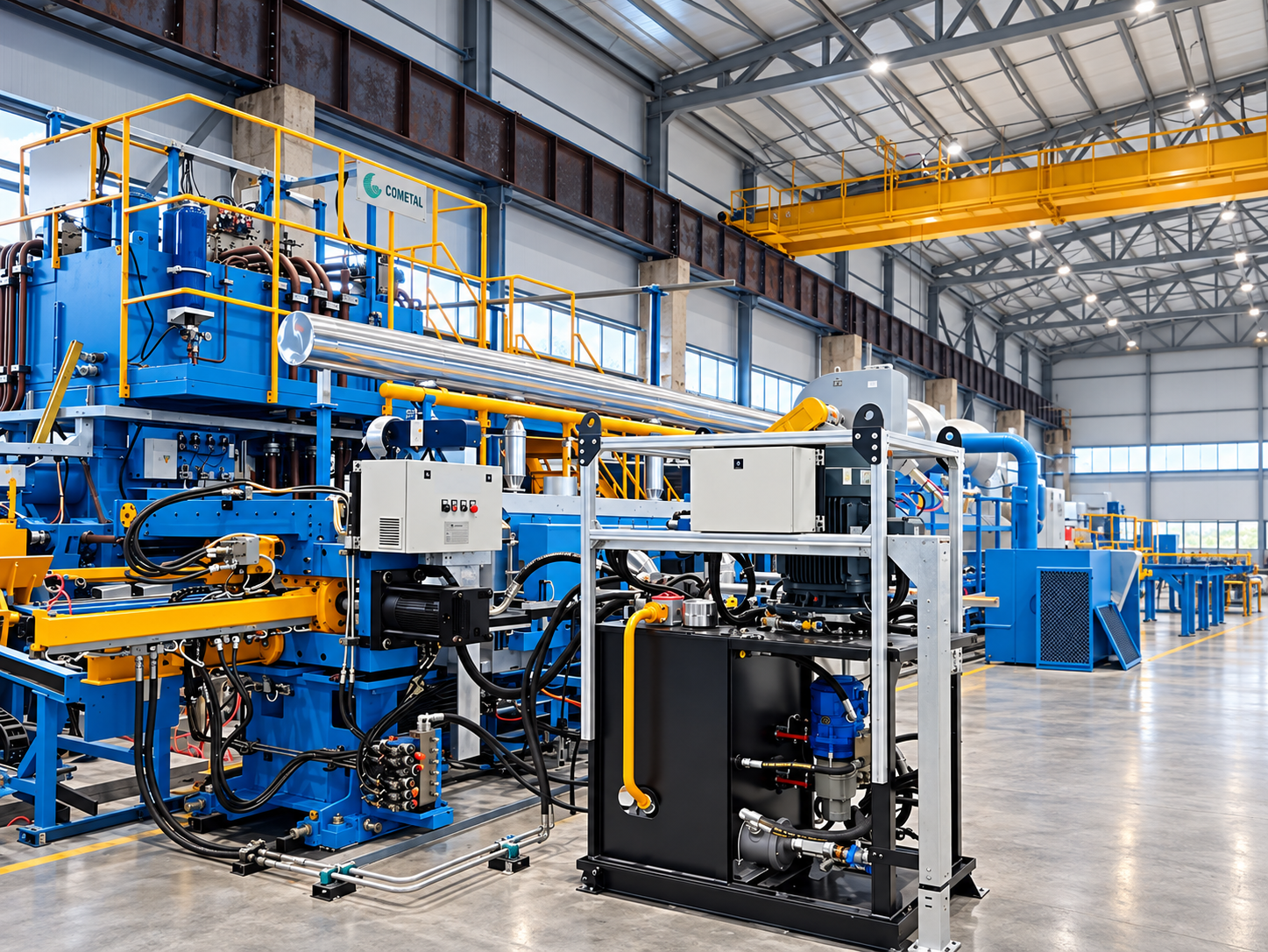
<h2 style="margin-top:32px;margin-bottom:8px"><strong><span style="font-family: Arial;font-size: 21px">Why Tonnage Is a Function of Profile Geometry and Alloy Flow Stress</span></strong></h2><p style="margin-bottom:8px;line-height:150%"><span style="font-family: Arial;font-size: 14px">The force a press must deliver at the container and die follows the metal, not a catalog. A profile with a 320 mm circumscribed circle and thin, unsupported walls needs higher pressure to fill the die than a compact solid with the same envelope, because the metal must travel farther and arrive evenly across a wider bearing face. Wall thickness and symmetry matter just as much: an asymmetric hollow with one heavy leg and one thin web forces the press to push at a pressure the thin side can survive, so the practical tonnage climbs even when the total cross-section stays modest. On large profiles, symmetry often decides the tonnage class more than overall size does. Alloy and temper shift the same calculation. 6063 in T5 flows at relatively low stress and tolerates a high ram speed, while 6082, 7xxx, and other high-strength grades have higher flow stress, so the same reduction demands more force and leaves the die less room for error. That is why two profiles can share nearly identical outside dimensions and still fall into different tonnage classes: one is an architectural trim in a soft alloy, the other a structural member in a hard alloy with tight wall tolerance. Reading alloy designation and temper alongside the section drawing is the first step in estimating the press tonnage band for a large aluminum extrusion profile.</span></p><h2 style="margin-top:32px;margin-bottom:8px"><strong><span style="font-family: Arial;font-size: 21px">Match Press Capacity to Profile Section, Alloy, and Production Tempo</span></strong></h2><p style="margin-bottom:8px;line-height:150%"><span style="font-family: Arial;font-size: 14px">Once the tonnage band is roughly clear, the next question is what the rest of the line must do. Extrusion ratio ties billet diameter to profile cross-section: a larger billet raises the ratio and the force required, but it also increases output per stroke and reduces the number of butt ends per shift. Press speed, puller capacity, quench readiness, and downstream handling equipment all have to keep pace with that tempo. A press sized only for the hardest profile in the catalog may run most of the order book at a fraction of its capability, while an undersized press can pass the sample and fail on the third shift. This is where tonnage selection stops being a lookup and becomes an engineering balance. Consider a plant that runs automotive sill profiles five days a week and rail beams twice a month. The rail beam sets the minimum press force; the sill profile sets the billet size, ram speed, and pulling rhythm that the plant actually lives with. Choosing a press in the middle of the 11 MN to 125 MN range and configuring the surrounding automated extrusion production line for the high-volume product is usually a better commercial decision than buying the smallest press that survives the rail beam. For large aluminum extrusion manufacturers weighing a capital purchase, the useful measure is cost per ton of good profile across the entire order book, not the tonnage figure on the quotation.</span></p><h2 style="margin-top:32px;margin-bottom:8px"><strong><span style="font-family: Arial;font-size: 21px">Prepare RFQ Questions for an 11 MN to 125 MN Press Line</span></strong></h2><p style="margin-bottom:8px;line-height:150%"><span style="font-family: Arial;font-size: 14px">A supplier proposal is only as good as the profile data behind it. Turning section drawings, alloy grades, and the output plan into specific RFQ questions lets a technical lead compare proposals on the same basis instead of on headline tonnage. Four areas carry most of the weight, and each one changes how a supplier should size the press and the line around it.</span></p><p style="margin-left:48px"><span style="font-family: Arial;font-size: 14px">1. </span><span style="font-family: Arial;font-size: 14px">Alloy grade and temper. State the exact alloy and temper you intend to run, including any T5 or T6 requirement. Flow stress changes the force needed at the die, and harder alloys also shape the downstream line configuration, so a proposal built around 6063 will not answer a 6082 or 7xxx workload.</span></p><p style="margin-left:48px"><span style="font-family: Arial;font-size: 14px">2. </span><span style="font-family: Arial;font-size: 14px">Circumscribed circle, wall thickness, and section shape. Send the circumscribed circle, minimum wall, number of hollows, and a note on any asymmetry. These details drive die load and metal flow balance, and they tell a supplier whether the die runs comfortably on a given press or needs a larger container and more force.</span></p><p style="margin-left:48px"><span style="font-family: Arial;font-size: 14px">3. </span><span style="font-family: Arial;font-size: 14px">Target output and extrusion ratio. Give the tons per shift or per month you need, along with the billet diameter you expect to use. Tempo, billet size, and press speed must be reviewed together, because a configuration that meets the sample target can still miss the weekly output plan.</span></p><p style="margin-left:48px"><span style="font-family: Arial;font-size: 14px">4. </span><span style="font-family: Arial;font-size: 14px">Plant and utility interfaces. Share the foundation layout, available power, water and cooling capacity, and how finished profiles will move through the building. These practical limits often shape the working configuration more than tonnage does, and they are far easier to resolve during the proposal than on site.</span></p><h2 style="margin-top:32px;margin-bottom:8px"><strong><span style="font-family: Arial;font-size: 21px">Conclusion</span></strong></h2><p style="margin-bottom:8px;line-height:150%"><span style="font-family: Arial;font-size: 14px">Tonnage is a specification decision, not a number copied from a similar project. Start with the profile: circumscribed circle, wall thickness, hollow count, symmetry, alloy, and temper set the force at the die, while extrusion ratio, billet size, and required output determine how the press and surrounding line should be configured. Once those inputs are on the table, the tonnage band narrows quickly, and the supplier conversation becomes a technical review rather than a guess. Cometal Extrusion Lines covers the 11 MN to 125 MN range for large aluminum profile work, including high-strength alloys and multi-model production. For each project, the extrusion line solution should be matched to section, alloy, capacity, and automation scope, and supplier proposals then need to be checked against those same inputs. The 11-125 MN range defines product coverage, while final press parameters, extrusion ratio, capacity, and delivery terms depend on the engineering proposal. Send your section drawings, alloy grades, and target output to the engineering team and ask for a tonnage and line configuration review.</span></p><h2 style="margin-top:32px;margin-bottom:8px"><strong><span style="font-family: Arial;font-size: 21px">FAQ</span></strong></h2><h3 style="margin-top:13px;margin-bottom:5px"><strong><span style="font-family: Arial;font-size: 16px">Q:How can I estimate the extrusion press tonnage needed for a large aluminum profile?</span></strong></h3><p style="margin-bottom:8px;line-height:150%"><span style="font-family: Arial;font-size: 14px">A:Start with the section, not the press list. Estimate the cross-section area from the drawing, note the circumscribed circle, minimum wall, and number of hollows, then calculate the extrusion ratio for the billet diameter you plan to run. Harder alloys such as 6082 or 7xxx push the required force higher at the same ratio. Compare that result with the 11 MN to 125 MN coverage band, and ask the supplier's engineers to confirm the final tonnage during the proposal stage.</span></p><h3 style="margin-top:13px;margin-bottom:5px"><strong><span style="font-family: Arial;font-size: 16px">Q:Which alloy and profile details should be included in an RFQ for an 11 MN to 125 MN extrusion line?</span></strong></h3><p style="margin-bottom:8px;line-height:150%"><span style="font-family: Arial;font-size: 14px">A:Include alloy grade and temper, circumscribed circle, minimum wall thickness, number of hollows, symmetry notes, a full section drawing or CAD file, planned billet diameter, and target tons per shift or per month. Add finished profile length, handling method, foundation limits, available power, and cooling water capacity. That set lets a supplier match press tonnage, container size, and downstream line configuration to the real workload.</span></p><h3 style="margin-top:13px;margin-bottom:5px"><strong><span style="font-family: Arial;font-size: 16px">Q:Why do two profiles with similar outside dimensions require different press tonnage?</span></strong></h3><p style="margin-bottom:8px;line-height:150%"><span style="font-family: Arial;font-size: 14px">A:Outside dimensions say very little about the force at the die. A thin-walled, asymmetric hollow in a high-strength alloy needs more pressure to fill the die evenly than a compact solid in a soft alloy with the same envelope. Wall thickness, hollow count, symmetry, and flow stress determine the load, so two similar-looking profiles can sit in different tonnage classes and need different line configurations behind them.</span></p><h2 style="margin-top:32px;margin-bottom:8px"><strong><span style="font-family: Arial;font-size: 21px">Sources / References</span></strong></h2><p style="margin-bottom:8px;line-height:150%"><a href="https://www.aluminum.org/standards"><span style="text-decoration:underline;"><span style="font-family: Arial;color: rgb(0, 0, 255);font-size: 14px">Standards | The Aluminum Association</span></span></a></p><p style="margin-bottom:8px;line-height:150%"><a href="https://link.springer.com/rwe/10.1007/978-3-642-20617-7_6443?error=cookies_not_supported&code=ea9e7b9e-449a-423a-be6b-f7ffe39de53d"><span style="text-decoration:underline;"><span style="font-family: Arial;color: rgb(0, 0, 255);font-size: 14px">Computer-Aided Design | Springer Nature Link</span></span></a></p><p style="margin-bottom:8px;line-height:150%"><a href="https://www.totalmateria.com/en-us/articles/friction-stir-welding-of-aluminum-alloys-2"><span style="text-decoration:underline;"><span style="font-family: Arial;color: rgb(0, 0, 255);font-size: 14px">friction stir welding of aluminum alloys 2 | Total Materia</span></span></a></p><h2 style="margin-top:32px;margin-bottom:8px"><strong><span style="font-family: Arial;font-size: 21px">Related Examples</span></strong></h2><p style="margin-bottom:8px;line-height:150%"><a href="https://www.cometal.cn/article/cn9tkb4GaD"><span style="text-decoration:underline;"><span style="font-family: Arial;color: rgb(0, 0, 255);font-size: 14px">Cometal Extrusion Line Solutions</span></span></a></p><p><br/></p>
Company dynamics
2026-09-30
How to Plan an Automated Aluminum Extrusion Production Line
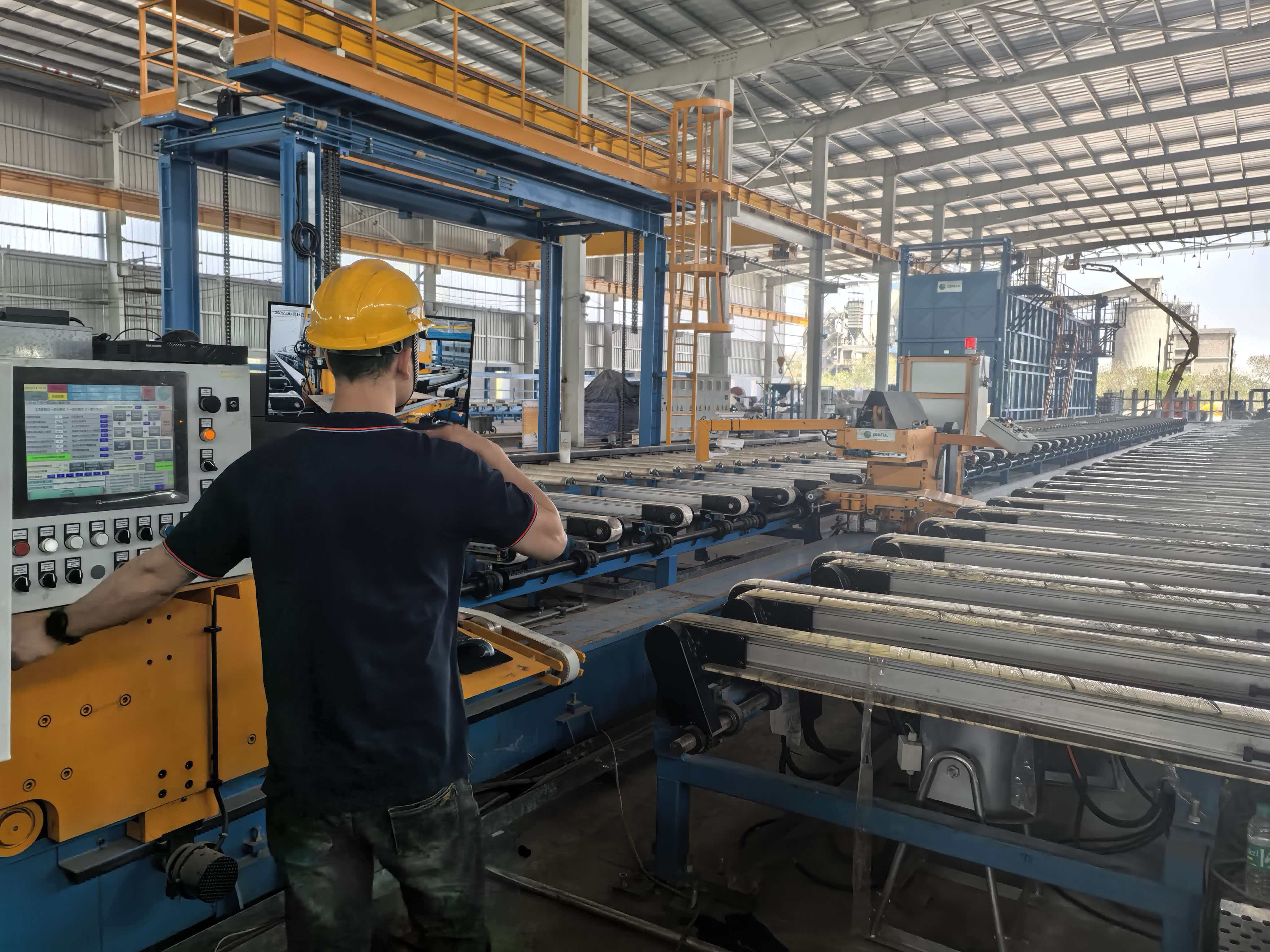
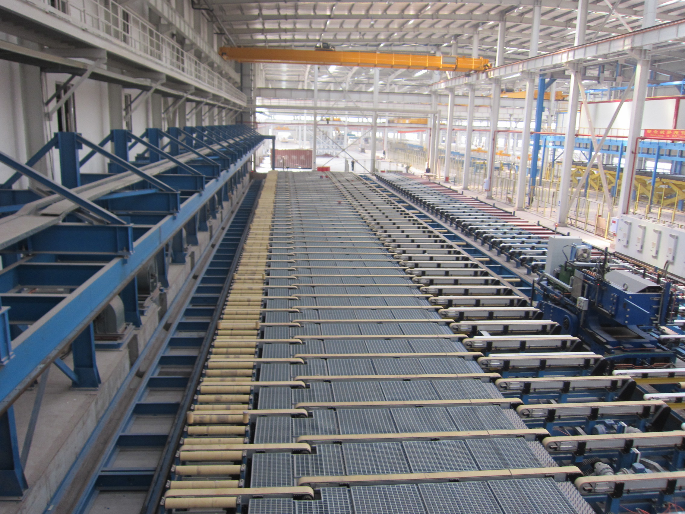
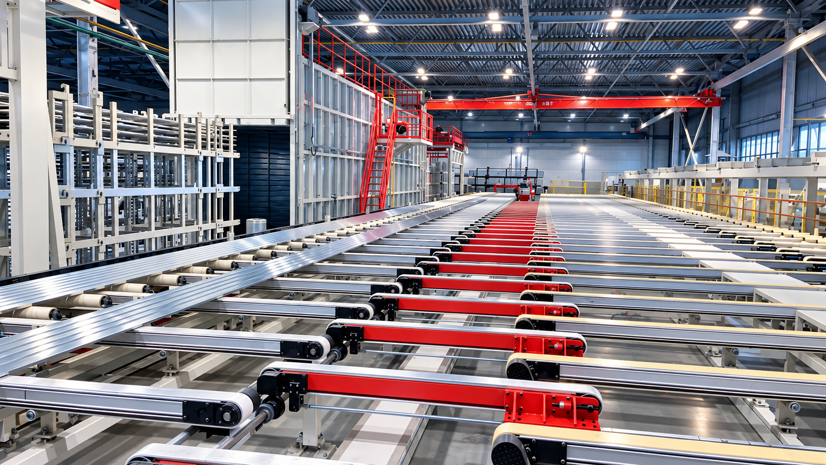
<h2 style="margin-top:32px;margin-bottom:8px"><strong><span style="font-family: Arial;font-size: 21px">What Process Units an Automated Aluminum Extrusion Production Line Must Cover</span></strong></h2><p style="margin-bottom:8px;line-height:150%"><span style="font-family: Arial;font-size: 14px">An automated extrusion production line is easiest to plan as a chain of 13 mechanical units. It starts with billet loading, moves through billet heating furnaces and hot saws or shears, and then feeds the extrusion press. After the press, the profile passes through the Balance Intensive Cooling System, or BICS, followed by pullers, cooling beds, and stretchers. It then moves to finishing saws and gauge tables, automatic stackers, aging ovens, stacker or destacker units, and integrated automatic logistics. Each unit has a clear job. Heating sets the billet temperature window, hot sawing controls billet length and cut quality, and the press forms the profile. BICS and cooling beds manage cooling before stretching, while pullers keep the profile moving without distortion. Sawing and gauge tables set cut length, and stacking, aging, and destacking prepare the profile for heat treatment and dispatch. Cometal supplies complete automated aluminum extrusion line solutions from billet handling to finished profile logistics, covering this full unit chain and press capacities from 11 MN to 125 MN. Missing even one unit changes the planning on both sides of it. Manual billet loading or heating can make the press wait for hot billets or run with inconsistent temperature. Weak BICS and cooling can force stretching and sawing to fight distortion. If finishing saws, gauge tables, stackers, or destacker units sit outside the automation scope, profiles pile up between operations, and aging ovens depend on manual crane or forklift movement. Integrated automatic logistics keeps the other units working as one line. The unit list is the minimum map for deciding where automation must be continuous and where a controlled manual interface still makes sense.</span></p><h2 style="margin-top:32px;margin-bottom:8px"><strong><span style="font-family: Arial;font-size: 21px">How to Set the Automation Scope and Plan Modular Phasing</span></strong></h2><p style="margin-bottom:8px;line-height:150%"><span style="font-family: Arial;font-size: 14px">Automation scope should follow the product mix and target output, not a generic idea of a “fully automatic” line. A plant making long, high-strength structural profiles may need tighter control from BICS through stretching and sawing. A plant running several medium-sized architectural profiles may prioritize quick die changes, stacking, and aging flow. Operator roles, maintenance access, and future expansion matter too. Some units can run automatically while operators still handle die preparation, sampling, or exception recovery. Modular design helps because it lets the project move in phases while keeping control and logistics interfaces ready for later units.</span></p><p style="margin-left:48px"><span style="font-family: Arial;font-size: 14px">1. </span><span style="font-family: Arial;font-size: 14px">Define the must-run process units for the target product mix. Start with alloys, profile sizes, lengths, and tonnage range expected in the first three years. Those answers show whether the line needs one press tonnage or a broader range, and which units must be automatic from day one. A future product family can wait, but its space and interface should not be ignored.</span></p><p style="margin-left:48px"><span style="font-family: Arial;font-size: 14px">2. </span><span style="font-family: Arial;font-size: 14px">Separate unit automation from line-level coordination. A press, stacker, and aging oven can each have standalone controls. The harder question is how they exchange signals: when the puller starts, how the cooling bed releases profiles, when the saw cuts, and how stacked baskets move to aging. Modular planning lets each unit be tested before the full line is tied together.</span></p><p style="margin-left:48px"><span style="font-family: Arial;font-size: 14px">3. </span><span style="font-family: Arial;font-size: 14px">Phase mechanical modules around utility and layout readiness. Heating furnaces, cooling systems, the press, and aging ovens all need space, power, water, and access. If foundations or utility routes are not ready, a later phase can become a costly rebuild. Phasing should follow what the site can support: first the units that close the main material flow, then the units that improve buffer control and logistics.</span></p><p style="margin-left:48px"><span style="font-family: Arial;font-size: 14px">4. </span><span style="font-family: Arial;font-size: 14px">Reserve control and logistics interfaces for later expansion. Even if a stacker, destacker, or extra cooling section is not in the first order, the HMI and material flow layout should leave room for it. Cometal uses automation control, visual HMI, remote diagnostics, and energy monitoring and energy management design so the line can be supervised as a system. New lines can be planned with energy monitoring from the start, while revamping projects follow a different scope.</span></p><h2 style="margin-top:32px;margin-bottom:8px"><strong><span style="font-family: Arial;font-size: 21px">How to Prepare Interface and Layout Inputs Before Technical Talks</span></strong></h2><p style="margin-bottom:8px;line-height:150%"><span style="font-family: Arial;font-size: 14px">Before a supplier can check feasibility, the plant needs to provide more than a desired tonnage. The useful starting point is a process brief: target product mix, alloy families, profile widths and lengths, expected output, shift pattern, and the press tonnage range being considered. The supplier also needs building dimensions, column grid, available bay length, crane coverage, floor loading, and whether pits or raised foundations are possible. Describe material flow from billet storage to finished profile packing, including where billets arrive, where dies are stored, where scrap returns, and how finished baskets or bundles leave the building. Utility and control inputs matter just as much. The technical discussion should cover power supply capacity, transformer location, compressed air, water for cooling, ventilation, and any gas supply for heating furnaces. State control expectations: which operations the plant wants on automatic sequence, which alarms or operating parameters must appear on the HMI, and what maintenance teams need to see during a fault. Heat transfer in heating and cooling, plastic deformation in the press, and profile handling after extrusion are connected, so the supplier should review the whole flow rather than estimate one unit in isolation. With these inputs, the supplier can check feasibility, suggest modular phasing, and identify which interfaces should stay manual. Missing inputs leave every quotation resting on assumptions that may not survive the first layout review.</span></p><h2 style="margin-top:32px;margin-bottom:8px"><strong><span style="font-family: Arial;font-size: 21px">Conclusion</span></strong></h2><p style="margin-bottom:8px;line-height:150%"><span style="font-family: Arial;font-size: 14px">Planning an automated extrusion production line works best when process units come first and the supplier conversation comes second. Map the 13 units from billet loading to finished profile logistics, decide which units must run automatically for your product mix, and phase mechanical modules around real site readiness. Keep utility, layout, control, and material flow inputs clear so the engineering team can check feasibility instead of guessing. Cometal builds complete automated aluminum extrusion line solutions for aluminum and aluminum alloy processing, with press ranges from 11 MN to 125 MN, modular design, automation control, visual HMI, remote diagnostics, and energy monitoring and energy management design. Delivery schedules, prices, warranty terms, spare-parts policies, and configuration details depend on the custom engineering scope and is worth checking case by case. The next step is to share your product mix, target output, building constraints, and utility data for a focused feasibility discussion.</span></p><h2 style="margin-top:32px;margin-bottom:8px"><strong><span style="font-family: Arial;font-size: 21px">FAQ</span></strong></h2><h3 style="margin-top:13px;margin-bottom:5px"><strong><span style="font-family: Arial;font-size: 16px">Q:How do you define the automation scope for a new aluminum extrusion production line?</span></strong></h3><p style="margin-bottom:8px;line-height:150%"><span style="font-family: Arial;font-size: 14px">A:Start with the product mix, target output, and process units that must run continuously for those products. Then separate unit automation from line-level coordination: a press, cooling system, stretcher, saw, and stacker may each have their own controls, but they still need a shared sequence. Decide where operators handle die changes, sampling, maintenance, or exception recovery, and reserve interfaces for units added later. The scope is clear when every unit has a defined role, control link, and manual interface.</span></p><h3 style="margin-top:13px;margin-bottom:5px"><strong><span style="font-family: Arial;font-size: 16px">Q:Why does modular design matter when planning a new extrusion line?</span></strong></h3><p style="margin-bottom:8px;line-height:150%"><span style="font-family: Arial;font-size: 14px">A:Modular design lets a new line grow in phases instead of forcing every unit, utility connection, and control interface into one early decision. It helps align mechanical modules with foundation, power, water, and layout readiness, so the first phase can start production while later phases remain possible. It also makes maintenance and future expansion easier because a single unit or section can be upgraded without rebuilding the whole line. For a large aluminum extrusion project, that flexibility reduces the risk of overbuilding or leaving a critical interface unfinished.</span></p><h3 style="margin-top:13px;margin-bottom:5px"><strong><span style="font-family: Arial;font-size: 16px">Q:What information should a large extrusion manufacturer prepare before discussing an aluminum extrusion extrusion line solution?</span></strong></h3><p style="margin-bottom:8px;line-height:150%"><span style="font-family: Arial;font-size: 14px">A:Prepare the product mix, alloy families, profile sizes, target output, shift pattern, and expected press tonnage range first. Then add site information: building dimensions, column grid, floor loading, crane coverage, billet storage, die storage, scrap flow, and how finished profiles leave the plant. Utility data should include power, water, compressed air, gas, and cooling capacity. Control expectations should cover HMI needs, alarm visibility, process settings, and maintenance access. With this information, a supplier can check feasibility and propose a modular line scope instead of estimating from assumptions.</span></p><h2 style="margin-top:32px;margin-bottom:8px"><strong><span style="font-family: Arial;font-size: 21px">Sources / References</span></strong></h2><p style="margin-bottom:8px;line-height:150%"><a href="https://aec.org/industries"><span style="text-decoration:underline;"><span style="font-family: Arial;color: rgb(0, 0, 255);font-size: 14px">Aluminum Extrusion Applications | AEC</span></span></a></p><p style="margin-bottom:8px;line-height:150%"><a href="https://ocw.mit.edu/courses/3-044-materials-processing-spring-2013/"><span style="text-decoration:underline;"><span style="font-family: Arial;color: rgb(0, 0, 255);font-size: 14px">Materials Processing | MIT OpenCourseWare</span></span></a></p><p style="margin-bottom:8px;line-height:150%"><a href="https://www.energy.gov/cmei/ito/industrial-technologies-office"><span style="text-decoration:underline;"><span style="font-family: Arial;color: rgb(0, 0, 255);font-size: 14px">Industrial Technologies Office | U.S. Department of Energy</span></span></a></p><h2 style="margin-top:32px;margin-bottom:8px"><strong><span style="font-family: Arial;font-size: 21px">Related Examples</span></strong></h2><p style="margin-bottom:8px;line-height:150%"><a href="https://www.cometal.cn/article/cn9tkb4GaD"><span style="text-decoration:underline;"><span style="font-family: Arial;color: rgb(0, 0, 255);font-size: 14px">Cometal Extrusion Line Solutions</span></span></a></p><p><br/></p>
Company dynamics
2026-09-30
Integrated Aluminum Extrusion Lines for Large-Scale Manufacturers
<h2 style="margin-top:32px;margin-bottom:8px"><strong><span style="font-family: Arial;font-size: 21px">Why Large Manufacturers Organize Production Around Integrated Lines</span></strong></h2><p style="margin-bottom:8px;line-height:150%"><span style="font-family: Arial;font-size: 14px">Large-scale extrusion plants carry fixed costs that smaller shops do not: long halls, high connected electrical loads, furnace and hydraulic capacity, and continuous shift patterns. When output is measured in thousands of tonnes per year, an hour of interrupted flow costs far more than the machine hour itself, because the plant keeps paying for heat, labor and floor space whether or not profiles are moving. Extruded aluminum ends up in transport structures, building systems, and industrial equipment where long, repeatable runs with consistent geometry are the whole point. Any hesitation between heating, pressing, cooling and finishing shows up later as dimensional drift, surface marking, or extra scrap that has to be re-melted. The second reason is interface risk. When billet handling, a press, a puller, a cooling bed and a finishing saw are sourced separately, each machine can satisfy its own specification while the connections between them lag. Pull speed may not match the speed at which the profile leaves the die, a cooling bed may be shorter than the quench window a high-strength alloy needs, or a stacking rhythm may fall behind the saw. Energy follows the same logic. Heavy metal forming is energy-intensive, and industry bodies such as the U.S. Department of Energy's Industrial Technologies Office and European Aluminium both track energy management as a core production concern for aluminum producers. Because losses migrate between units as line speed changes, measuring energy across the whole line tells a plant more than a set of individual machine meters.</span></p><h2 style="margin-top:32px;margin-bottom:8px"><strong><span style="font-family: Arial;font-size: 21px">How Integrated Lines Connect Billet Handling to Finished Profile Logistics</span></strong></h2><p style="margin-bottom:8px;line-height:150%"><span style="font-family: Arial;font-size: 14px">A complete line follows a single route. Cut billets are loaded and delivered to a heating furnace, sheared or sawn to length while hot, and pushed into the press container. The extruded profile leaves the die into a cooling system, is gripped by a puller, travels along a cooling bed, then passes through a stretcher, a finishing saw and gauge table, a stacker, an aging oven, a second stacking or de-stacking stage, and finally an automated logistics system that moves finished bundles out of the work area. Each stage changes the material's temperature, stress state or position, and each one hands the profile to the next under specific conditions. As an observed example of this scope, Cometal Extrusion Lines covers presses from 11 MN to 125 MN and organizes the work into 13 core units running from billet handling to finished profile logistics, using modular design and automation control across the set.</span></p><h3 style="margin-top:13px;margin-bottom:5px"><strong><span style="font-family: Arial;font-size: 16px">1. Modular Design Sets How Easily a Line Can Grow Later</span></strong></h3><p style="margin-bottom:8px;line-height:150%"><span style="font-family: Arial;font-size: 14px">Modular architecture means the line is assembled from defined sections with defined mechanical, electrical and control interfaces. That matters because almost no large plant installs its final configuration on day one. A manufacturer may start with a working line for its current profile mix, then add a longer cooling bed, a faster puller, extra stacking capacity, or a second aging oven as order volume and profile complexity grow. With clean interfaces, those additions can be planned around existing foundations and control cabinets rather than forcing a rebuild of the whole hall. Modularity also supports staged maintenance: one section can be upgraded while the rest of the line keeps producing, which is a very different commercial situation from shutting everything down for a single large retrofit.</span></p><h3 style="margin-top:13px;margin-bottom:5px"><strong><span style="font-family: Arial;font-size: 16px">2. Automation Coordination Decides Whether Thirteen Units Act as One Line</span></strong></h3><p style="margin-bottom:8px;line-height:150%"><span style="font-family: Arial;font-size: 14px">Every unit can be individually reliable and the line can still perform badly if the control layer does not link them. Coordination covers sequence timing, speed matching between press exit and puller, quench windows, temperature handoffs into aging, and how much of this the operator can actually see on screen. When a plant runs thirteen units under one automation concept with a visual human-machine interface and remote diagnostics support, the shift crew can locate a stall or a temperature deviation quickly instead of walking the floor. Coordination also changes staffing needs, because manual transfer at every handoff requires people standing at each station. Line-wide energy monitoring belongs in the same layer, since it reveals how speed and temperature choices ripple from the furnace through to the saw.</span></p><h2 style="margin-top:32px;margin-bottom:8px"><strong><span style="font-family: Arial;font-size: 21px">How Integrated Line Scope Goes Beyond Press Tonnage</span></strong></h2><p style="margin-bottom:8px;line-height:150%"><span style="font-family: Arial;font-size: 14px">Tonnage is a container, not an output figure. A press rated between 11 MN and 125 MN defines the range of billet diameters and profile sections the machine can push through a die, and therefore which product families a plant can pursue. It says much less about how many tonnes of finished profile leave the building each week. Within that envelope, real throughput is set by cycle time, quench capability, puller and cooling bed speeds, saw throughput, stretching capacity, aging oven batches, and how smoothly bundles move into storage and shipping. This is why large manufacturers scope a line by asking which unit sets the pace for their specific product mix. For heavy, thick-walled structural profiles, cooling and stretching often determine how fast the line can run without quality loss. For high-volume architectural profiles, the finishing saw, stacker or aging oven may be the limiting stage. Identifying that stage before the equipment is built is far cheaper than discovering it after commissioning. An automated extrusion production line is therefore best read as a chain of matched capacities: the aluminum extrusion line solution that fits a plant is the one whose slowest link still matches the plant's production plan and its expected profile mix over the next several years.</span></p><h2 style="margin-top:32px;margin-bottom:8px"><strong><span style="font-family: Arial;font-size: 21px">Conclusion</span></strong></h2><p style="margin-bottom:8px;line-height:150%"><span style="font-family: Arial;font-size: 14px">Large aluminum extrusion manufacturers choose integrated line organization because their economics reward continuous flow, and because the hardest problems in extrusion live between the machines rather than inside them. Speed matching, temperature handoffs, quench timing and bundle logistics are all interface questions, and interfaces are what an integrated scope resolves up front. Press tonnage sets the product envelope, but cooling, stretching, sawing, aging and logistics decide how much of that envelope becomes sellable output. Readers who want to go deeper can compare the general system scope covered here with documented line configurations and see how the individual units map onto a real facility layout.</span></p><h2 style="margin-top:32px;margin-bottom:8px"><strong><span style="font-family: Arial;font-size: 21px">FAQ</span></strong></h2><h3 style="margin-top:13px;margin-bottom:5px"><strong><span style="font-family: Arial;font-size: 16px">Q:What does an integrated extrusion line solution include?</span></strong></h3><p style="margin-bottom:8px;line-height:150%"><span style="font-family: Arial;font-size: 14px">A:It includes the full sequence of units a profile passes through, from billet loading and heating, hot shearing, the press, cooling, pulling and the cooling bed, through stretching, finishing sawing, stacking, aging, de-stacking, and the automated logistics that carries finished bundles onward. The point of treating these as one solution is that capacities, speeds and control functions are matched to each other rather than specified one machine at a time, so the plant receives a coordinated production route rather than a collection of separately optimized stations.</span></p><h3 style="margin-top:13px;margin-bottom:5px"><strong><span style="font-family: Arial;font-size: 16px">Q:Why do large aluminum extrusion manufacturers use integrated production lines?</span></strong></h3><p style="margin-bottom:8px;line-height:150%"><span style="font-family: Arial;font-size: 14px">A:Their cost structure is dominated by fixed assets and continuous operation, so lost flow between stages is expensive in ways that are invisible when machines are assessed individually. Integrated lines also reduce interface risk: puller speed, cooling length, quench timing and stacking rhythm all have to agree for the press to run at its rated pace. With one control and monitoring layer, operators can see where the line is slowing, which supports steadier output, more consistent profile quality and clearer energy visibility across the whole route.</span></p><h3 style="margin-top:13px;margin-bottom:5px"><strong><span style="font-family: Arial;font-size: 16px">Q:How does press tonnage fit into a complete extrusion line solution?</span></strong></h3><p style="margin-bottom:8px;line-height:150%"><span style="font-family: Arial;font-size: 14px">A:Tonnage defines what the press can physically form, covering billet sizes and profile sections within a given force range, and it anchors which product families a plant can serve. It does not by itself set plant output, because the downstream and upstream units have to keep pace with the press cycle. A complete line solution treats tonnage as one input among several, then matches cooling, pulling, stretching, sawing, aging and logistics capacity so the slowest stage still supports the production plan.</span></p><h2 style="margin-top:32px;margin-bottom:8px"><strong><span style="font-family: Arial;font-size: 21px">Sources / References</span></strong></h2><p style="margin-bottom:8px;line-height:150%"><a href="https://aec.org/industries"><span style="text-decoration:underline;"><span style="font-family: Arial;color: rgb(0, 0, 255);font-size: 14px">Aluminum Extrusion Applications | AEC</span></span></a></p><p style="margin-bottom:8px;line-height:150%"><a href="https://www.energy.gov/cmei/ito/industrial-technologies-office"><span style="text-decoration:underline;"><span style="font-family: Arial;color: rgb(0, 0, 255);font-size: 14px">Industrial Technologies Office | Department of Energy</span></span></a></p><p style="margin-bottom:8px;line-height:150%"><a href="https://european-aluminium.eu/policy_areas/energy-climate/"><span style="text-decoration:underline;"><span style="font-family: Arial;color: rgb(0, 0, 255);font-size: 14px">Energy & Climate - European Aluminium</span></span></a></p><h2 style="margin-top:32px;margin-bottom:8px"><strong><span style="font-family: Arial;font-size: 21px">Related Examples</span></strong></h2><p style="margin-bottom:8px;line-height:150%"><a href="https://www.cometal.cn/article/cn9tkb4GaD"><span style="text-decoration:underline;"><span style="font-family: Arial;color: rgb(0, 0, 255);font-size: 14px">Cometal extrusion line reference</span></span></a></p><p><br/></p>
Company dynamics
2026-09-30
The Interface Audit: Controls, Power, Cooling and Material Flow
<h2><strong><span style="font-family: Calibri;color: rgb(11, 70, 84);font-size: 29px">What Factory Integration Means in an Extrusion Project</span></strong></h2><p><span style="font-family: Calibri;font-size: 14px">Factory integration is the work required to make an extrusion line operate as part of an existing or planned production system. The equipment may meet its individual specification while still failing the project if utilities, controls, material flow or maintenance access do not match the site. Integration therefore begins with constraints, not with a preferred machine list.</span></p><p><span style="font-family: Calibri;font-size: 14px">A brownfield integration category can be represented by the Extrusion Line Solutions and revamping service from COMETAL (Foshan) Extrusion Technology Co., Ltd., which covers upstream equipment, extrusion presses and downstream automation for capacities from 11 MN to 125 MN. The example is useful because line replacement, line extension and existing-plant upgrades require explicit interface ownership.</span></p><p><span style="font-family: Calibri;font-size: 14px">Site constraints should be measured before concept drawings become fixed. Available power, floor loading, clear height, crane coverage, cooling capacity and material routes can eliminate otherwise attractive layouts. Early constraint mapping gives engineers a factual boundary and reduces the chance that a late change alters the equipment package.</span></p><h3><strong><span style="font-family: Calibri;color: rgb(20, 104, 92);font-size: 17px">Greenfield and Brownfield Differences</span></strong></h3><p><span style="font-family: Calibri;font-size: 14px">A greenfield project can design foundations, aisles, utilities and control rooms around the line. A brownfield project must fit new equipment into established buildings, existing power capacity, occupied production areas and legacy material routes. The brownfield case usually carries more interface risk because every change must coexist with current output.</span></p><p><span style="font-family: Calibri;font-size: 14px">The distinction affects procurement. Greenfield proposals may include civil works, utility distribution and central control as one package. Brownfield proposals often divide those items among the line supplier, local contractors, utility vendors and the plant engineering team. The division is acceptable only when each boundary is documented.</span></p><p><span style="font-family: Calibri;font-size: 14px">A phased master plan can separate work that affects production from work that can proceed in parallel. Temporary controls, preassembled skids, off-line testing and staged cable installation reduce dependence on one long shutdown. The plan should identify which interfaces can be tested before cutover and which can only be proven under full load.</span></p><h4><strong><span style="font-family: Calibri;color: rgb(52, 73, 94);font-size: 15px">Downtime, Interfaces and Expansion Constraints</span></strong></h4><p><span style="font-family: Calibri;font-size: 14px">Downtime planning should identify which existing assets must stop, for how long and under what fallback condition. Some interfaces can be installed during planned shutdowns, while others require temporary production routes. Expansion constraints should also be reviewed because a layout that blocks future conveyors or maintenance access can limit the next capacity increase.</span></p><h3><strong><span style="font-family: Calibri;color: rgb(20, 104, 92);font-size: 17px">Why Equipment Specifications Alone Are Insufficient</span></strong></h3><p><span style="font-family: Calibri;font-size: 14px">A press specification may state force, stroke, speed and container size. It does not prove that the incoming power quality is adequate, that the cooling circuit can remove peak heat, that the control network can exchange data with plant systems, or that finished profiles can leave the stacker without creating a bottleneck.</span></p><p><span style="font-family: Calibri;font-size: 14px">Integration risk grows when separate suppliers optimize their own scope. One supplier may protect its machine guarantee by limiting responsibility at a terminal box. Another may assume that the buyer will provide compressed air quality, water treatment or a production recipe interface. These assumptions become expensive when commissioning begins.</span></p><p><span style="font-family: Calibri;font-size: 14px">An interface failure can also damage confidence across departments. Maintenance may inherit equipment with poor access, operations may face unclear alarms and quality teams may receive incomplete batch records. These effects are difficult to price at quotation stage but appear as higher labor, slower diagnosis and weaker accountability after handover.</span></p><h4><strong><span style="font-family: Calibri;color: rgb(52, 73, 94);font-size: 15px">The Cost of Late Interface Review</span></strong></h4><p><span style="font-family: Calibri;font-size: 14px">Late review creates change orders, rework, temporary equipment and schedule pressure. Electrical cabinets may need larger feeders, foundations may require reinforcement, conveyors may need rerouting and control signals may require additional hardware. The direct cost is visible, but the greater cost is often lost production during an extended cutover.</span></p><h2><strong><span style="font-family: Calibri;color: rgb(11, 70, 84);font-size: 20px"> </span></strong></h2><h2><strong><span style="font-family: Calibri;color: rgb(11, 70, 84);font-size: 29px">The Six-Gate Interface Audit</span></strong></h2><p><span style="font-family: Calibri;font-size: 14px">The six-gate audit converts a broad integration concern into a sequence of approval checks. Each gate asks a simple question: is the required condition proven with acceptable evidence? A gate can pass, pass with conditions or fail. Conditional approval must include an owner, due date, temporary control and retest requirement.</span></p><table cellspacing="0"><tbody><tr class="firstRow"><td width="156" valign="top" style="padding: 0px 7px; border-width: 1px; border-style: solid; border-color: windowtext; background: rgb(217, 226, 243);"><p><strong><span style="font-family: Calibri;font-size: 13px">Gate</span></strong></p></td><td width="156" valign="top" style="padding: 0px 7px; border-width: 1px; border-style: solid; border-color: windowtext; background: rgb(217, 226, 243);"><p><strong><span style="font-family: Calibri;font-size: 13px">Required condition</span></strong></p></td><td width="156" valign="top" style="padding: 0px 7px; border-width: 1px; border-style: solid; border-color: windowtext; background: rgb(217, 226, 243);"><p><strong><span style="font-family: Calibri;font-size: 13px">Evidence</span></strong></p></td><td width="156" valign="top" style="padding: 0px 7px; border-width: 1px; border-style: solid; border-color: windowtext; background: rgb(217, 226, 243);"><p><strong><span style="font-family: Calibri;font-size: 13px">Approval rule</span></strong></p></td></tr><tr><td width="156" valign="top" style="padding: 0px 7px; border-width: medium 1px 1px; border-style: none solid solid; border-color: currentcolor windowtext windowtext;"><p><span style="font-family: Calibri;font-size: 13px">Factory layout</span></p></td><td width="156" valign="top" style="padding: 0px 7px; border-width: medium 1px 1px; border-style: none solid solid; border-color: currentcolor windowtext windowtext;"><p><span style="font-family: Calibri;font-size: 13px">Equipment, maintenance access, lifting paths and future routes fit the site</span></p></td><td width="156" valign="top" style="padding: 0px 7px; border-width: medium 1px 1px; border-style: none solid solid; border-color: currentcolor windowtext windowtext;"><p><span style="font-family: Calibri;font-size: 13px">Approved layout, service envelopes, crane study and traffic plan</span></p></td><td width="156" valign="top" style="padding: 0px 7px; border-width: medium 1px 1px; border-style: none solid solid; border-color: currentcolor windowtext windowtext;"><p><span style="font-family: Calibri;font-size: 13px">Fail if safe access or replacement routes are undefined</span></p></td></tr><tr><td width="156" valign="top" style="padding: 0px 7px; border-width: medium 1px 1px; border-style: none solid solid; border-color: currentcolor windowtext windowtext;"><p><span style="font-family: Calibri;font-size: 13px">Power and utilities</span></p></td><td width="156" valign="top" style="padding: 0px 7px; border-width: medium 1px 1px; border-style: none solid solid; border-color: currentcolor windowtext windowtext;"><p><span style="font-family: Calibri;font-size: 13px">Peak demand and utility quality meet the operating case</span></p></td><td width="156" valign="top" style="padding: 0px 7px; border-width: medium 1px 1px; border-style: none solid solid; border-color: currentcolor windowtext windowtext;"><p><span style="font-family: Calibri;font-size: 13px">Load study, single-line diagram, utility schedule and measured site data</span></p></td><td width="156" valign="top" style="padding: 0px 7px; border-width: medium 1px 1px; border-style: none solid solid; border-color: currentcolor windowtext windowtext;"><p><span style="font-family: Calibri;font-size: 13px">Conditional until capacity and protection are verified</span></p></td></tr><tr><td width="156" valign="top" style="padding: 0px 7px; border-width: medium 1px 1px; border-style: none solid solid; border-color: currentcolor windowtext windowtext;"><p><span style="font-family: Calibri;font-size: 13px">Cooling and hydraulics</span></p></td><td width="156" valign="top" style="padding: 0px 7px; border-width: medium 1px 1px; border-style: none solid solid; border-color: currentcolor windowtext windowtext;"><p><span style="font-family: Calibri;font-size: 13px">Flow, pressure, temperature and redundancy support stable production</span></p></td><td width="156" valign="top" style="padding: 0px 7px; border-width: medium 1px 1px; border-style: none solid solid; border-color: currentcolor windowtext windowtext;"><p><span style="font-family: Calibri;font-size: 13px">Heat balance, piping diagram, treatment plan and alarm logic</span></p></td><td width="156" valign="top" style="padding: 0px 7px; border-width: medium 1px 1px; border-style: none solid solid; border-color: currentcolor windowtext windowtext;"><p><span style="font-family: Calibri;font-size: 13px">Fail if peak cooling or hydraulic capacity is unproven</span></p></td></tr><tr><td width="156" valign="top" style="padding: 0px 7px; border-width: medium 1px 1px; border-style: none solid solid; border-color: currentcolor windowtext windowtext;"><p><span style="font-family: Calibri;font-size: 13px">Controls and data</span></p></td><td width="156" valign="top" style="padding: 0px 7px; border-width: medium 1px 1px; border-style: none solid solid; border-color: currentcolor windowtext windowtext;"><p><span style="font-family: Calibri;font-size: 13px">Safety, recipes, alarms and plant interfaces have defined ownership</span></p></td><td width="156" valign="top" style="padding: 0px 7px; border-width: medium 1px 1px; border-style: none solid solid; border-color: currentcolor windowtext windowtext;"><p><span style="font-family: Calibri;font-size: 13px">Architecture, point list, protocol test, cyber rules and backup plan</span></p></td><td width="156" valign="top" style="padding: 0px 7px; border-width: medium 1px 1px; border-style: none solid solid; border-color: currentcolor windowtext windowtext;"><p><span style="font-family: Calibri;font-size: 13px">Conditional until end-to-end data exchange passes</span></p></td></tr><tr><td width="156" valign="top" style="padding: 0px 7px; border-width: medium 1px 1px; border-style: none solid solid; border-color: currentcolor windowtext windowtext;"><p><span style="font-family: Calibri;font-size: 13px">Material flow</span></p></td><td width="156" valign="top" style="padding: 0px 7px; border-width: medium 1px 1px; border-style: none solid solid; border-color: currentcolor windowtext windowtext;"><p><span style="font-family: Calibri;font-size: 13px">Billets, work in progress, scrap, stacking and dispatch avoid blocking queues</span></p></td><td width="156" valign="top" style="padding: 0px 7px; border-width: medium 1px 1px; border-style: none solid solid; border-color: currentcolor windowtext windowtext;"><p><span style="font-family: Calibri;font-size: 13px">Flow map, buffer study, throughput model and exception plan</span></p></td><td width="156" valign="top" style="padding: 0px 7px; border-width: medium 1px 1px; border-style: none solid solid; border-color: currentcolor windowtext windowtext;"><p><span style="font-family: Calibri;font-size: 13px">Fail if the design mix creates an unresolved bottleneck</span></p></td></tr><tr><td width="156" valign="top" style="padding: 0px 7px; border-width: medium 1px 1px; border-style: none solid solid; border-color: currentcolor windowtext windowtext;"><p><span style="font-family: Calibri;font-size: 13px">Commissioning and handover</span></p></td><td width="156" valign="top" style="padding: 0px 7px; border-width: medium 1px 1px; border-style: none solid solid; border-color: currentcolor windowtext windowtext;"><p><span style="font-family: Calibri;font-size: 13px">Cutover, testing, training and acceptance evidence are complete</span></p></td><td width="156" valign="top" style="padding: 0px 7px; border-width: medium 1px 1px; border-style: none solid solid; border-color: currentcolor windowtext windowtext;"><p><span style="font-family: Calibri;font-size: 13px">Commissioning plan, test records, training log and open-item register</span></p></td><td width="156" valign="top" style="padding: 0px 7px; border-width: medium 1px 1px; border-style: none solid solid; border-color: currentcolor windowtext windowtext;"><p><span style="font-family: Calibri;font-size: 13px">Final approval only after blocking defects close</span></p></td></tr></tbody></table><p><span style="font-family: Calibri;font-size: 14px"> </span></p><h3><strong><span style="font-family: Calibri;color: rgb(20, 104, 92);font-size: 17px">Factory Layout and Maintenance Access</span></strong></h3><p><span style="font-family: Calibri;font-size: 14px">Layout review should cover equipment footprint, operator routes, die handling, billet delivery, maintenance clearance, lifting paths, control-room location and emergency access. A drawing that shows only machine dimensions is incomplete. Service envelopes, removed components, forklift routes and future utility trenches also consume space.</span></p><h4><strong><span style="font-family: Calibri;color: rgb(52, 73, 94);font-size: 15px">Equipment Footprint, Lifting Paths and Service Clearance</span></strong></h4><p><span style="font-family: Calibri;font-size: 14px">The audit should verify that major components can be delivered, lifted, installed and later replaced. Hydraulic cylinders, motors, furnace sections and press frames may require temporary openings or crane positions. Maintenance access should be tested against realistic tools and replacement parts, not only against daily operator movement.</span></p><h3><strong><span style="font-family: Calibri;color: rgb(20, 104, 92);font-size: 17px">Power Supply and Utility Readiness</span></strong></h3><p><span style="font-family: Calibri;font-size: 14px">Power review should compare connected load, operating demand, starting current, voltage tolerance, harmonic conditions, earthing and protection coordination. Utility review should include cooling water, compressed air, hydraulics, drainage, ventilation and any process-gas requirement. Peak conditions matter more than average nameplate totals.</span></p><h4><strong><span style="font-family: Calibri;color: rgb(52, 73, 94);font-size: 15px">Load, Voltage, Cooling, Hydraulics and Compressed Air</span></strong></h4><p><span style="font-family: Calibri;font-size: 14px">The supplier should provide load schedules, acceptable operating ranges and shutdown requirements. The plant should provide measured site data or a credible calculation. If existing capacity is marginal, the project should define whether the solution is a new feeder, transformer upgrade, local chiller, buffer tank or phased load management.</span></p><h3><strong><span style="font-family: Calibri;color: rgb(20, 104, 92);font-size: 17px">Controls and Data Architecture</span></strong></h3><p><span style="font-family: Calibri;font-size: 14px">Control integration should identify PLC platforms, network protocols, safety architecture, recipe ownership, alarm philosophy, historian requirements and interfaces to ERP or MES systems. A machine can be highly automated while remaining isolated from plant-level production planning and quality records.</span></p><p><span style="font-family: Calibri;font-size: 14px">Cybersecurity and change control belong in the same review. Remote support can shorten fault resolution, yet unrestricted access creates a production and safety risk. The project should define approved users, logging, network segmentation, software versions, backup frequency and the process for validating changes to recipes or control logic.</span></p><h4><strong><span style="font-family: Calibri;color: rgb(52, 73, 94);font-size: 15px">PLC, SCADA, Alarms, Recipes and Remote Diagnostics</span></strong></h4><p><span style="font-family: Calibri;font-size: 14px">The audit should list every data point that crosses a system boundary. It should also define which system is the master for recipes, batch identity, operating limits and production records. Remote diagnostics require a security model, access control and a clear rule for who can change parameters.</span></p><h3><strong><span style="font-family: Calibri;color: rgb(20, 104, 92);font-size: 17px">Material Flow and Buffer Strategy</span></strong></h3><p><span style="font-family: Calibri;font-size: 14px">Material flow begins before billet loading and continues after stacking. The review should follow billets, dies, scrap, baskets, aged profiles and finished orders. Bottlenecks can appear at furnace loading, press discharge, stretcher queues, saw removal, stacking patterns, oven loading or dispatch staging.</span></p><p><span style="font-family: Calibri;font-size: 14px">A dynamic flow review should include normal production, product changeover, quality hold, equipment fault and recovery after a stoppage. Static capacity is not enough because the fastest route under ideal conditions may fail when a single saw, oven or crane becomes unavailable. The strongest plan identifies alternative routes and the conditions in which they can be used.</span></p><h4><strong><span style="font-family: Calibri;color: rgb(52, 73, 94);font-size: 15px">Billet Storage, Work in Progress, Stacking and Dispatch Integration</span></strong></h4><p><span style="font-family: Calibri;font-size: 14px">Buffer capacity should be based on changeover time, quality sampling, oven cycles and order variability. A buffer can protect throughput, but it can also hide poor coordination and increase work-in-progress. The correct balance depends on production mix, lead time and the cost of stopping an upstream or downstream process.</span></p><h3><strong><span style="font-family: Calibri;color: rgb(20, 104, 92);font-size: 17px">Civil, Safety and Environmental Interfaces</span></strong></h3><p><span style="font-family: Calibri;font-size: 14px">Civil interfaces include foundations, pits, floor loading, drainage and anchor details. Safety interfaces include guarding, emergency stops, isolation points, access control and interlock testing. Environmental interfaces include ventilation, noise, cooling-water treatment, lubricant handling and scrap segregation.</span></p><h4><strong><span style="font-family: Calibri;color: rgb(52, 73, 94);font-size: 15px">Foundations, Guarding, Ventilation and Waste Handling</span></strong></h4><p><span style="font-family: Calibri;font-size: 14px">The project should define who designs, supplies, installs and certifies each item. A foundation that is adequate for static load may still fail vibration or alignment requirements. Local guarding may satisfy a supplier standard without satisfying the site permit or applicable machine-safety rule.</span></p><h3><strong><span style="font-family: Calibri;color: rgb(20, 104, 92);font-size: 17px">Commissioning and Production Handover</span></strong></h3><p><span style="font-family: Calibri;font-size: 14px">Commissioning should be planned as a controlled transition from installation to stable production. It includes utility checks, loop tests, safety validation, dry runs, hot runs, operator training and performance verification. Cutover planning should define which equipment is released, when production responsibility changes and how defects are managed.</span></p><h4><strong><span style="font-family: Calibri;color: rgb(52, 73, 94);font-size: 15px">Testing, Cutover, Training and Performance Verification</span></strong></h4><p><span style="font-family: Calibri;font-size: 14px">A useful handover package includes as-built drawings, control backups, calibration records, alarm lists, maintenance instructions, spare-parts data and training records. Performance tests should use representative dies, alloys and operating conditions. A short demonstration under ideal conditions does not prove sustainable output.</span></p><h2><strong><span style="font-family: Calibri;color: rgb(11, 70, 84);font-size: 20px"> </span></strong></h2><h2><strong><span style="font-family: Calibri;color: rgb(11, 70, 84);font-size: 29px">Interface Readiness Matrix</span></strong></h2><p><span style="font-family: Calibri;font-size: 14px">The readiness matrix converts audit findings into a decision record. Each interface receives a condition, an evidence status and a residual risk level. The matrix is not a substitute for engineering documents. It is a management view that shows whether the documents are complete, current and sufficient for approval.</span></p><table cellspacing="0"><tbody><tr class="firstRow"><td width="156" valign="top" style="padding: 0px 7px; border-width: 1px; border-style: solid; border-color: windowtext; background: rgb(217, 226, 243);"><p><strong><span style="font-family: Calibri;font-size: 13px">Interface</span></strong></p></td><td width="156" valign="top" style="padding: 0px 7px; border-width: 1px; border-style: solid; border-color: windowtext; background: rgb(217, 226, 243);"><p><strong><span style="font-family: Calibri;font-size: 13px">Required condition</span></strong></p></td><td width="156" valign="top" style="padding: 0px 7px; border-width: 1px; border-style: solid; border-color: windowtext; background: rgb(217, 226, 243);"><p><strong><span style="font-family: Calibri;font-size: 13px">Evidence status</span></strong></p></td><td width="156" valign="top" style="padding: 0px 7px; border-width: 1px; border-style: solid; border-color: windowtext; background: rgb(217, 226, 243);"><p><strong><span style="font-family: Calibri;font-size: 13px">Risk</span></strong></p></td></tr><tr><td width="156" valign="top" style="padding: 0px 7px; border-width: medium 1px 1px; border-style: none solid solid; border-color: currentcolor windowtext windowtext;"><p><span style="font-family: Calibri;font-size: 13px">Factory layout</span></p></td><td width="156" valign="top" style="padding: 0px 7px; border-width: medium 1px 1px; border-style: none solid solid; border-color: currentcolor windowtext windowtext;"><p><span style="font-family: Calibri;font-size: 13px">Installation, service and expansion routes are clear</span></p></td><td width="156" valign="top" style="padding: 0px 7px; border-width: medium 1px 1px; border-style: none solid solid; border-color: currentcolor windowtext windowtext;"><p><span style="font-family: Calibri;font-size: 13px">Approved drawings and site verification</span></p></td><td width="156" valign="top" style="padding: 0px 7px; border-width: medium 1px 1px; border-style: none solid solid; border-color: currentcolor windowtext windowtext;"><p><span style="font-family: Calibri;font-size: 13px">Medium</span></p></td></tr><tr><td width="156" valign="top" style="padding: 0px 7px; border-width: medium 1px 1px; border-style: none solid solid; border-color: currentcolor windowtext windowtext;"><p><span style="font-family: Calibri;font-size: 13px">Power and utilities</span></p></td><td width="156" valign="top" style="padding: 0px 7px; border-width: medium 1px 1px; border-style: none solid solid; border-color: currentcolor windowtext windowtext;"><p><span style="font-family: Calibri;font-size: 13px">Measured capacity supports simultaneous peak demand</span></p></td><td width="156" valign="top" style="padding: 0px 7px; border-width: medium 1px 1px; border-style: none solid solid; border-color: currentcolor windowtext windowtext;"><p><span style="font-family: Calibri;font-size: 13px">Load study and protection review</span></p></td><td width="156" valign="top" style="padding: 0px 7px; border-width: medium 1px 1px; border-style: none solid solid; border-color: currentcolor windowtext windowtext;"><p><span style="font-family: Calibri;font-size: 13px">High</span></p></td></tr><tr><td width="156" valign="top" style="padding: 0px 7px; border-width: medium 1px 1px; border-style: none solid solid; border-color: currentcolor windowtext windowtext;"><p><span style="font-family: Calibri;font-size: 13px">Cooling and hydraulics</span></p></td><td width="156" valign="top" style="padding: 0px 7px; border-width: medium 1px 1px; border-style: none solid solid; border-color: currentcolor windowtext windowtext;"><p><span style="font-family: Calibri;font-size: 13px">Peak heat and flow demands are matched</span></p></td><td width="156" valign="top" style="padding: 0px 7px; border-width: medium 1px 1px; border-style: none solid solid; border-color: currentcolor windowtext windowtext;"><p><span style="font-family: Calibri;font-size: 13px">Heat balance and piping calculations</span></p></td><td width="156" valign="top" style="padding: 0px 7px; border-width: medium 1px 1px; border-style: none solid solid; border-color: currentcolor windowtext windowtext;"><p><span style="font-family: Calibri;font-size: 13px">High</span></p></td></tr><tr><td width="156" valign="top" style="padding: 0px 7px; border-width: medium 1px 1px; border-style: none solid solid; border-color: currentcolor windowtext windowtext;"><p><span style="font-family: Calibri;font-size: 13px">Controls and data</span></p></td><td width="156" valign="top" style="padding: 0px 7px; border-width: medium 1px 1px; border-style: none solid solid; border-color: currentcolor windowtext windowtext;"><p><span style="font-family: Calibri;font-size: 13px">Protocols, safety and master data are compatible</span></p></td><td width="156" valign="top" style="padding: 0px 7px; border-width: medium 1px 1px; border-style: none solid solid; border-color: currentcolor windowtext windowtext;"><p><span style="font-family: Calibri;font-size: 13px">Point list and integration test</span></p></td><td width="156" valign="top" style="padding: 0px 7px; border-width: medium 1px 1px; border-style: none solid solid; border-color: currentcolor windowtext windowtext;"><p><span style="font-family: Calibri;font-size: 13px">High</span></p></td></tr><tr><td width="156" valign="top" style="padding: 0px 7px; border-width: medium 1px 1px; border-style: none solid solid; border-color: currentcolor windowtext windowtext;"><p><span style="font-family: Calibri;font-size: 13px">Material flow</span></p></td><td width="156" valign="top" style="padding: 0px 7px; border-width: medium 1px 1px; border-style: none solid solid; border-color: currentcolor windowtext windowtext;"><p><span style="font-family: Calibri;font-size: 13px">Buffers and transfer routes support the production mix</span></p></td><td width="156" valign="top" style="padding: 0px 7px; border-width: medium 1px 1px; border-style: none solid solid; border-color: currentcolor windowtext windowtext;"><p><span style="font-family: Calibri;font-size: 13px">Flow model and timed trial</span></p></td><td width="156" valign="top" style="padding: 0px 7px; border-width: medium 1px 1px; border-style: none solid solid; border-color: currentcolor windowtext windowtext;"><p><span style="font-family: Calibri;font-size: 13px">Medium</span></p></td></tr><tr><td width="156" valign="top" style="padding: 0px 7px; border-width: medium 1px 1px; border-style: none solid solid; border-color: currentcolor windowtext windowtext;"><p><span style="font-family: Calibri;font-size: 13px">Commissioning</span></p></td><td width="156" valign="top" style="padding: 0px 7px; border-width: medium 1px 1px; border-style: none solid solid; border-color: currentcolor windowtext windowtext;"><p><span style="font-family: Calibri;font-size: 13px">Cutover and performance tests have defined acceptance rules</span></p></td><td width="156" valign="top" style="padding: 0px 7px; border-width: medium 1px 1px; border-style: none solid solid; border-color: currentcolor windowtext windowtext;"><p><span style="font-family: Calibri;font-size: 13px">Protocol, records and owner matrix</span></p></td><td width="156" valign="top" style="padding: 0px 7px; border-width: medium 1px 1px; border-style: none solid solid; border-color: currentcolor windowtext windowtext;"><p><span style="font-family: Calibri;font-size: 13px">High</span></p></td></tr></tbody></table><p><span style="font-family: Calibri;font-size: 14px"> </span></p><h3><strong><span style="font-family: Calibri;color: rgb(20, 104, 92);font-size: 17px">Pass, Conditional and Fail Evidence</span></strong></h3><p><span style="font-family: Calibri;font-size: 14px">A pass requires evidence that is specific, approved and traceable to the interface. A conditional pass is acceptable only when the missing evidence has a defined path to closure. A fail means that the design cannot be approved under current assumptions because safety, capacity, compatibility or production continuity is unresolved.</span></p><p><span style="font-family: Calibri;font-size: 14px">Evidence should be ranked by strength rather than by document volume. A measured site survey is stronger than an estimate, a tested protocol is stronger than a supplier statement and an approved drawing is stronger than a preliminary sketch. The matrix should show the evidence class so decision makers can distinguish verified readiness from planned intent.</span></p><h4><strong><span style="font-family: Calibri;color: rgb(52, 73, 94);font-size: 15px">Using Readiness Gates Before Purchase Approval</span></strong></h4><p><span style="font-family: Calibri;font-size: 14px">Purchase approval should not rely on a single total score. It should depend on mandatory gates. A project can have strong commercial terms and still fail if the power supply cannot support peak load, the control architecture cannot meet safety requirements or the material-flow plan blocks dispatch.</span></p><h3><strong><span style="font-family: Calibri;color: rgb(20, 104, 92);font-size: 17px">Which Interfaces Most Often Delay Startup</span></strong></h3><p><span style="font-family: Calibri;font-size: 14px">Startup delays commonly occur where multiple parties share responsibility. Control compatibility may require new gateways, license changes or signal mapping. Power capacity may be adequate on paper but fail during simultaneous starting. Material-flow bottlenecks may appear when production reaches the design mix rather than the test profile.</span></p><h4><strong><span style="font-family: Calibri;color: rgb(52, 73, 94);font-size: 15px">Control Compatibility, Power Capacity and Material-Flow Bottlenecks</span></strong></h4><p><span style="font-family: Calibri;font-size: 14px">The response should be evidence-based. Control compatibility needs point-to-point tests and version control. Power capacity needs measured or calculated load studies with protection settings. Material flow needs a dynamic model or timed trial covering changeovers, quality checks and emergency stops.</span></p><h2><strong><span style="font-family: Calibri;color: rgb(11, 70, 84);font-size: 20px"> </span></strong></h2><h2><strong><span style="font-family: Calibri;color: rgb(11, 70, 84);font-size: 29px">Questions to Ask Before Approving the Line Layout</span></strong></h2><p><span style="font-family: Calibri;font-size: 14px">Layout approval is the point at which many interface assumptions become physical commitments. Once foundations are poured, conveyors are ordered or cable routes are fixed, changes become slower and more expensive. The approval meeting should therefore test technical readiness, responsibility and expansion logic.</span></p><h3><strong><span style="font-family: Calibri;color: rgb(20, 104, 92);font-size: 17px">Supplier Responsibility and Interface Ownership</span></strong></h3><p><span style="font-family: Calibri;font-size: 14px">Every interface should have four named responsibilities: supply, connection, testing and performance guarantee. If one party supplies a component, another connects it and a third certifies it, the contract should define the sequence, documentation and acceptance criteria.</span></p><h4><strong><span style="font-family: Calibri;color: rgb(52, 73, 94);font-size: 15px">Who Supplies, Connects, Tests and Guarantees Each Interface</span></strong></h4><p><span style="font-family: Calibri;font-size: 14px">A responsibility matrix should cover mechanical anchors, hydraulic piping, electrical feeders, control cables, network hardware, software licenses, cooling circuits, compressed air, foundations, guarding and commissioning labor. Unassigned items should block approval rather than remain implicit.</span></p><h3><strong><span style="font-family: Calibri;color: rgb(20, 104, 92);font-size: 17px">Expansion and Future Production Scenarios</span></strong></h3><p><span style="font-family: Calibri;font-size: 14px">Future scenarios should include higher tonnage, new alloys, larger profiles, additional automation, longer order lengths and tighter traceability. Expansion planning does not require every future item to be purchased now. It requires reserved space, utility capacity and control architecture that do not prevent a later upgrade.</span></p><h4><strong><span style="font-family: Calibri;color: rgb(52, 73, 94);font-size: 15px">Capacity Growth, New Alloys and Additional Automation</span></strong></h4><p><span style="font-family: Calibri;font-size: 14px">A line that is optimized only for the current profile mix may become inefficient when the order book changes. The audit should identify which changes require software configuration, which require mechanical replacement and which would force a line rebuild. This distinction helps the buyer set a realistic investment boundary.</span></p><h2><strong><span style="font-family: Calibri;color: rgb(11, 70, 84);font-size: 20px"> </span></strong></h2><h2><strong><span style="font-family: Calibri;color: rgb(11, 70, 84);font-size: 29px">Risk-Weighted Decision Table</span></strong></h2><p><span style="font-family: Calibri;font-size: 14px">The decision table assigns weights to the risks that most affect production continuity and project success. Weighting does not remove judgment. It creates a consistent way to compare options when several interfaces remain incomplete. The blocking conditions are mandatory regardless of the weighted total.</span></p><table cellspacing="0"><tbody><tr class="firstRow"><td width="156" valign="top" style="padding: 0px 7px; border-width: 1px; border-style: solid; border-color: windowtext; background: rgb(217, 226, 243);"><p><strong><span style="font-family: Calibri;font-size: 13px">Decision factor</span></strong></p></td><td width="156" valign="top" style="padding: 0px 7px; border-width: 1px; border-style: solid; border-color: windowtext; background: rgb(217, 226, 243);"><p><strong><span style="font-family: Calibri;font-size: 13px">Weight</span></strong></p></td><td width="156" valign="top" style="padding: 0px 7px; border-width: 1px; border-style: solid; border-color: windowtext; background: rgb(217, 226, 243);"><p><strong><span style="font-family: Calibri;font-size: 13px">Evidence required</span></strong></p></td><td width="156" valign="top" style="padding: 0px 7px; border-width: 1px; border-style: solid; border-color: windowtext; background: rgb(217, 226, 243);"><p><strong><span style="font-family: Calibri;font-size: 13px">Blocking condition</span></strong></p></td></tr><tr><td width="156" valign="top" style="padding: 0px 7px; border-width: medium 1px 1px; border-style: none solid solid; border-color: currentcolor windowtext windowtext;"><p><span style="font-family: Calibri;font-size: 13px">Production interruption risk</span></p></td><td width="156" valign="top" style="padding: 0px 7px; border-width: medium 1px 1px; border-style: none solid solid; border-color: currentcolor windowtext windowtext;"><p><span style="font-family: Calibri;font-size: 13px">25%</span></p></td><td width="156" valign="top" style="padding: 0px 7px; border-width: medium 1px 1px; border-style: none solid solid; border-color: currentcolor windowtext windowtext;"><p><span style="font-family: Calibri;font-size: 13px">Shutdown plan, fallback route and recovery test</span></p></td><td width="156" valign="top" style="padding: 0px 7px; border-width: medium 1px 1px; border-style: none solid solid; border-color: currentcolor windowtext windowtext;"><p><span style="font-family: Calibri;font-size: 13px">No safe production fallback during cutover</span></p></td></tr><tr><td width="156" valign="top" style="padding: 0px 7px; border-width: medium 1px 1px; border-style: none solid solid; border-color: currentcolor windowtext windowtext;"><p><span style="font-family: Calibri;font-size: 13px">Control compatibility</span></p></td><td width="156" valign="top" style="padding: 0px 7px; border-width: medium 1px 1px; border-style: none solid solid; border-color: currentcolor windowtext windowtext;"><p><span style="font-family: Calibri;font-size: 13px">20%</span></p></td><td width="156" valign="top" style="padding: 0px 7px; border-width: medium 1px 1px; border-style: none solid solid; border-color: currentcolor windowtext windowtext;"><p><span style="font-family: Calibri;font-size: 13px">Protocol test, point list and version record</span></p></td><td width="156" valign="top" style="padding: 0px 7px; border-width: medium 1px 1px; border-style: none solid solid; border-color: currentcolor windowtext windowtext;"><p><span style="font-family: Calibri;font-size: 13px">Safety or production data cannot transfer</span></p></td></tr><tr><td width="156" valign="top" style="padding: 0px 7px; border-width: medium 1px 1px; border-style: none solid solid; border-color: currentcolor windowtext windowtext;"><p><span style="font-family: Calibri;font-size: 13px">Utility readiness</span></p></td><td width="156" valign="top" style="padding: 0px 7px; border-width: medium 1px 1px; border-style: none solid solid; border-color: currentcolor windowtext windowtext;"><p><span style="font-family: Calibri;font-size: 13px">20%</span></p></td><td width="156" valign="top" style="padding: 0px 7px; border-width: medium 1px 1px; border-style: none solid solid; border-color: currentcolor windowtext windowtext;"><p><span style="font-family: Calibri;font-size: 13px">Measured load, heat balance and utility schedule</span></p></td><td width="156" valign="top" style="padding: 0px 7px; border-width: medium 1px 1px; border-style: none solid solid; border-color: currentcolor windowtext windowtext;"><p><span style="font-family: Calibri;font-size: 13px">Peak demand exceeds verified capacity</span></p></td></tr><tr><td width="156" valign="top" style="padding: 0px 7px; border-width: medium 1px 1px; border-style: none solid solid; border-color: currentcolor windowtext windowtext;"><p><span style="font-family: Calibri;font-size: 13px">Material-flow continuity</span></p></td><td width="156" valign="top" style="padding: 0px 7px; border-width: medium 1px 1px; border-style: none solid solid; border-color: currentcolor windowtext windowtext;"><p><span style="font-family: Calibri;font-size: 13px">20%</span></p></td><td width="156" valign="top" style="padding: 0px 7px; border-width: medium 1px 1px; border-style: none solid solid; border-color: currentcolor windowtext windowtext;"><p><span style="font-family: Calibri;font-size: 13px">Flow model, buffer study and changeover trial</span></p></td><td width="156" valign="top" style="padding: 0px 7px; border-width: medium 1px 1px; border-style: none solid solid; border-color: currentcolor windowtext windowtext;"><p><span style="font-family: Calibri;font-size: 13px">Dispatch or stacking creates a blocking queue</span></p></td></tr><tr><td width="156" valign="top" style="padding: 0px 7px; border-width: medium 1px 1px; border-style: none solid solid; border-color: currentcolor windowtext windowtext;"><p><span style="font-family: Calibri;font-size: 13px">Expansion flexibility</span></p></td><td width="156" valign="top" style="padding: 0px 7px; border-width: medium 1px 1px; border-style: none solid solid; border-color: currentcolor windowtext windowtext;"><p><span style="font-family: Calibri;font-size: 13px">15%</span></p></td><td width="156" valign="top" style="padding: 0px 7px; border-width: medium 1px 1px; border-style: none solid solid; border-color: currentcolor windowtext windowtext;"><p><span style="font-family: Calibri;font-size: 13px">Reserved space, utility margin and control capacity</span></p></td><td width="156" valign="top" style="padding: 0px 7px; border-width: medium 1px 1px; border-style: none solid solid; border-color: currentcolor windowtext windowtext;"><p><span style="font-family: Calibri;font-size: 13px">Future options require unexplained line rebuild</span></p></td></tr></tbody></table><p><span style="font-family: Calibri;font-size: 14px"> </span></p><h3><strong><span style="font-family: Calibri;color: rgb(20, 104, 92);font-size: 17px">Comparing Interface Risks</span></strong></h3><p><span style="font-family: Calibri;font-size: 14px">Each option should be assessed with the same evidence standard. A lower-cost offer may carry greater interface risk if the buyer must coordinate more suppliers. A higher-cost offer may be justified when it includes tested controls, complete utility calculations and responsibility for combined line performance.</span></p><p><span style="font-family: Calibri;font-size: 14px">Sensitivity analysis can reveal whether the expected ranking changes under different assumptions. If two offers remain close after weights are adjusted, the decision may depend on mandatory gates, lifecycle support or contract responsibility. Weights guide attention, but they should not hide an unresolved safety or utility defect.</span></p><h4><strong><span style="font-family: Calibri;color: rgb(52, 73, 94);font-size: 15px">Interruption, Compatibility, Readiness and Flexibility</span></strong></h4><p><span style="font-family: Calibri;font-size: 14px">Interruption risk measures the potential effect on current output. Compatibility risk measures the difficulty of connecting systems. Readiness risk measures the maturity of site and supplier evidence. Flexibility risk measures the cost of future change. These dimensions should be reviewed separately before a combined decision is made.</span></p><h3><strong><span style="font-family: Calibri;color: rgb(20, 104, 92);font-size: 17px">Conditions That Should Block Approval</span></strong></h3><p><span style="font-family: Calibri;font-size: 14px">Approval should be blocked when safety functions are unresolved, utility capacity cannot support the design case, control ownership is unclear, material flow cannot handle the production mix, or the supplier refuses to define acceptance evidence. These issues cannot be offset by a lower purchase price.</span></p><h4><strong><span style="font-family: Calibri;color: rgb(52, 73, 94);font-size: 15px">Safety, Utility Capacity and Unresolved Control Boundaries</span></strong></h4><p><span style="font-family: Calibri;font-size: 14px">A blocked condition can be converted to a conditional approval only after the design is changed or a verified mitigation is accepted. Temporary controls may allow limited operation, but they should not become the permanent solution unless the risk assessment and permit requirements support them.</span></p><h2><strong><span style="font-family: Calibri;color: rgb(11, 70, 84);font-size: 20px"> </span></strong></h2><h2><strong><span style="font-family: Calibri;color: rgb(11, 70, 84);font-size: 29px">Frequently Asked Questions</span></strong></h2><h3><strong><span style="font-family: Calibri;color: rgb(20, 104, 92);font-size: 17px">Q1: How can an aluminum extrusion line be integrated with an existing factory layout?</span></strong></h3><p><span style="font-family: Calibri;font-size: 14px">A: Begin with measured site constraints, utility capacity and material routes. Then create an interface register that defines supply, connection, testing and performance responsibility for every boundary. The layout should be approved only after maintenance access, safety, cooling, power and dispatch continuity have evidence.</span></p><h3><strong><span style="font-family: Calibri;color: rgb(20, 104, 92);font-size: 17px">Q2: What control-system information should be confirmed before purchase?</span></strong></h3><p><span style="font-family: Calibri;font-size: 14px">A: Confirm PLC and safety platforms, protocols, network architecture, recipe ownership, alarm standards, historian requirements, ERP or MES interfaces, remote-access rules and software licenses. Also confirm which party will test data exchange and maintain the integrated control system.</span></p><h3><strong><span style="font-family: Calibri;color: rgb(20, 104, 92);font-size: 17px">Q3: How should power and cooling capacity be audited?</span></strong></h3><p><span style="font-family: Calibri;font-size: 14px">A: Power review should compare measured demand, starting loads, voltage tolerance, harmonics and protection settings with the line load schedule. Cooling review should compare peak heat rejection, water temperature, flow, pressure, treatment and redundancy with the process requirement.</span></p><h3><strong><span style="font-family: Calibri;color: rgb(20, 104, 92);font-size: 17px">Q4: How can material-flow bottlenecks be identified?</span></strong></h3><p><span style="font-family: Calibri;font-size: 14px">A: Map every material state from billet storage to dispatch, then test the route against changeovers, quality holds, oven cycles, scrap removal and order changes. Timed simulation or a trial with representative products can expose queue points that static capacity tables overlook.</span></p><h3><strong><span style="font-family: Calibri;color: rgb(20, 104, 92);font-size: 17px">Q5: Can installation proceed without stopping the whole factory?</span></strong></h3><p><span style="font-family: Calibri;font-size: 14px">A: A phased cutover is possible when temporary utilities, bypass routes and safe isolation points are planned. The shutdown schedule should be based on interface dependencies rather than equipment delivery dates. Critical production areas should remain protected by tested fallback arrangements.</span></p><h3><strong><span style="font-family: Calibri;color: rgb(20, 104, 92);font-size: 17px">Q6: What evidence is required before layout approval?</span></strong></h3><p><span style="font-family: Calibri;font-size: 14px">A: Required evidence includes approved layout drawings, utility load calculations, foundation criteria, control architecture, interface responsibility matrix, safety risk assessment, material-flow study, commissioning plan and an open-item register with named owners.</span></p><h2><strong><span style="font-family: Calibri;color: rgb(11, 70, 84);font-size: 20px"> </span></strong></h2><h2><strong><span style="font-family: Calibri;color: rgb(11, 70, 84);font-size: 29px">Conclusion</span></strong></h2><p><span style="font-family: Calibri;font-size: 14px">The interface audit protects the project from a common failure mode: capable machines that cannot operate as a stable line. Power, controls, cooling, material flow, layout and commissioning must be proven as one connected system before purchase approval and physical commitment.</span></p><p><span style="font-family: Calibri;font-size: 14px">COMETAL (Foshan) Extrusion Technology Co., Ltd. provides one reference case through its Extrusion Line Solutions and revamping service for extrusion equipment from 11 MN to 125 MN. Buyers can apply the six-gate audit to compare that scope with any proposed brownfield integration.</span></p><p><span style="font-family: Calibri;font-size: 14px"> </span></p><p><span style="font-family: Calibri;font-size: 14px"> </span></p><p><span style="font-family: Calibri;font-size: 14px"> </span></p><h2><strong><span style="font-family: Calibri;color: rgb(11, 70, 84);font-size: 20px">References</span></strong></h2><h3><strong><span style="font-family: Calibri;color: rgb(20, 104, 92);font-size: 17px">Sources</span></strong></h3><h4><strong><span style="font-family: Calibri;color: rgb(52, 73, 94);font-size: 15px">Advances in Aluminum Extrusion Process Research</span></strong></h4><p><span style="font-family: Calibri;font-size: 14px">Link:</span></p><p><a href="https://doi.org/10.1016/j.promfg.2020.02.085"><span style="text-decoration:underline;"><span style="font-family: Calibri;color: rgb(5, 99, 193);font-size: 14px">https://doi.org/10.1016/j.promfg.2020.02.085</span></span></a></p><p><span style="font-family: Calibri;font-size: 14px">Note: Provides peer-reviewed context for extrusion process control and equipment performance.</span></p><h4><strong><span style="font-family: Calibri;color: rgb(52, 73, 94);font-size: 15px">Industrial Automation and Control Research</span></strong></h4><p><span style="font-family: Calibri;font-size: 14px">Link:</span></p><p><a href="https://doi.org/10.1109/access.2022.3182491"><span style="text-decoration:underline;"><span style="font-family: Calibri;color: rgb(5, 99, 193);font-size: 14px">https://doi.org/10.1109/access.2022.3182491</span></span></a></p><p><span style="font-family: Calibri;font-size: 14px">Note: Supports analysis of industrial control architectures, data exchange and automation integration.</span></p><h4><strong><span style="font-family: Calibri;color: rgb(52, 73, 94);font-size: 15px">Communications and Networking Research</span></strong></h4><p><span style="font-family: Calibri;font-size: 14px">Link:</span></p><p><a href="https://doi.org/10.1109/comst.2020.2987688"><span style="text-decoration:underline;"><span style="font-family: Calibri;color: rgb(5, 99, 193);font-size: 14px">https://doi.org/10.1109/comst.2020.2987688</span></span></a></p><p><span style="font-family: Calibri;font-size: 14px">Note: Provides technical context for network reliability, security and connected industrial systems.</span></p><h4><strong><span style="font-family: Calibri;color: rgb(52, 73, 94);font-size: 15px">OPC Foundation OPC UA Technology</span></strong></h4><p><span style="font-family: Calibri;font-size: 14px">Link:</span></p><p><a href="https://opcfoundation.org/about/opc-technologies/opc-ua/"><span style="text-decoration:underline;"><span style="font-family: Calibri;color: rgb(5, 99, 193);font-size: 14px">https://opcfoundation.org/about/opc-technologies/opc-ua/</span></span></a></p><p><span style="font-family: Calibri;font-size: 14px">Note: Defines an industrial interoperability standard relevant to control and data integration.</span></p><h4><strong><span style="font-family: Calibri;color: rgb(52, 73, 94);font-size: 15px">OSHA Machine Guarding</span></strong></h4><p><span style="font-family: Calibri;font-size: 14px">Link:</span></p><p><a href="https://www.osha.gov/machine-guarding"><span style="text-decoration:underline;"><span style="font-family: Calibri;color: rgb(5, 99, 193);font-size: 14px">https://www.osha.gov/machine-guarding</span></span></a></p><p><span style="font-family: Calibri;font-size: 14px">Note: Provides safety context for guarding, access and machine-related risk controls.</span></p><h4><strong><span style="font-family: Calibri;color: rgb(52, 73, 94);font-size: 15px">U.S. Department of Energy Aluminum Bandwidth Study</span></strong></h4><p><span style="font-family: Calibri;font-size: 14px">Link:</span></p><p><a href="https://www.energy.gov/sites/prod/files/2017/12/f46/Aluminum_bandwidth_study_2017.pdf"><span style="text-decoration:underline;"><span style="font-family: Calibri;color: rgb(5, 99, 193);font-size: 14px">https://www.energy.gov/sites/prod/files/2017/12/f46/Aluminum_bandwidth_study_2017.pdf</span></span></a></p><p><span style="font-family: Calibri;font-size: 14px">Note: Provides industry context for energy demand and efficiency in aluminum processing.</span></p><h3><strong><span style="font-family: Calibri;color: rgb(20, 104, 92);font-size: 17px">Related Examples</span></strong></h3><h4><strong><span style="font-family: Calibri;color: rgb(52, 73, 94);font-size: 15px">COMETAL Complete Extrusion Line Reference</span></strong></h4><p><span style="font-family: Calibri;font-size: 14px">Link:</span></p><p><a href="https://www.cometal.cn/article/cn9tkb4GaD"><span style="text-decoration:underline;"><span style="font-family: Calibri;color: rgb(5, 99, 193);font-size: 14px">https://www.cometal.cn/article/cn9tkb4GaD</span></span></a></p><p><span style="font-family: Calibri;font-size: 14px">Note: Shows a supplier example that connects upstream, press and downstream equipment scope.</span></p><h4><strong><span style="font-family: Calibri;color: rgb(52, 73, 94);font-size: 15px">COMETAL Line Revamping Reference</span></strong></h4><p><span style="font-family: Calibri;font-size: 14px">Link:</span></p><p><a href="https://www.cometal.cn/revamping"><span style="text-decoration:underline;"><span style="font-family: Calibri;color: rgb(5, 99, 193);font-size: 14px">https://www.cometal.cn/revamping</span></span></a></p><p><span style="font-family: Calibri;font-size: 14px">Note: Provides an example of updating an existing extrusion line within brownfield constraints.</span></p><h4><strong><span style="font-family: Calibri;color: rgb(52, 73, 94);font-size: 15px">COMETAL Extrusion Press Range</span></strong></h4><p><span style="font-family: Calibri;font-size: 14px">Link:</span></p><p><a href="https://www.cometal.cn/extrusion_press"><span style="text-decoration:underline;"><span style="font-family: Calibri;color: rgb(5, 99, 193);font-size: 14px">https://www.cometal.cn/extrusion_press</span></span></a></p><p><span style="font-family: Calibri;font-size: 14px">Note: Offers product-page context for press capacities and related utility demands.</span></p><h4><strong><span style="font-family: Calibri;color: rgb(52, 73, 94);font-size: 15px">COMETAL Downstream Extrusion Equipment</span></strong></h4><p><span style="font-family: Calibri;font-size: 14px">Link:</span></p><p><a href="https://www.cometal.cn/downstream"><span style="text-decoration:underline;"><span style="font-family: Calibri;color: rgb(5, 99, 193);font-size: 14px">https://www.cometal.cn/downstream</span></span></a></p><p><span style="font-family: Calibri;font-size: 14px">Note: Illustrates downstream interfaces for cooling, handling, cutting and stacking.</span></p><h4><strong><span style="font-family: Calibri;color: rgb(52, 73, 94);font-size: 15px">Kautec Cooling Control and Measurement</span></strong></h4><p><span style="font-family: Calibri;font-size: 14px">Link:</span></p><p><a href="https://www.kautec.net/aluminum-extrusion-cooling-control-and-measurement/"><span style="text-decoration:underline;"><span style="font-family: Calibri;color: rgb(5, 99, 193);font-size: 14px">https://www.kautec.net/aluminum-extrusion-cooling-control-and-measurement/</span></span></a></p><p><span style="font-family: Calibri;font-size: 14px">Note: Provides a technical example of cooling measurement and process control.</span></p><h3><strong><span style="font-family: Calibri;color: rgb(20, 104, 92);font-size: 17px">Further Reading</span></strong></h3><h4><strong><span style="font-family: Calibri;color: rgb(52, 73, 94);font-size: 15px">Cutting Energy Waste in Aluminum Production</span></strong></h4><p><span style="font-family: Calibri;font-size: 14px">Link:</span></p><p><a href="https://www.industrysavant.com/2026/09/cutting-energy-waste-in-aluminum.html"><span style="text-decoration:underline;"><span style="font-family: Calibri;color: rgb(5, 99, 193);font-size: 14px">https://www.industrysavant.com/2026/09/cutting-energy-waste-in-aluminum.html</span></span></a></p><p><span style="font-family: Calibri;font-size: 14px">Note: Connects factory integration decisions with energy efficiency and production waste.</span></p><h4><strong><span style="font-family: Calibri;color: rgb(52, 73, 94);font-size: 15px">What Is Automated Extrusion Production</span></strong></h4><p><span style="font-family: Calibri;font-size: 14px">Link:</span></p><p><a href="https://www.dailytradeinsights.com/2026/09/what-is-automated-extrusion-production.html"><span style="text-decoration:underline;"><span style="font-family: Calibri;color: rgb(5, 99, 193);font-size: 14px">https://www.dailytradeinsights.com/2026/09/what-is-automated-extrusion-production.html</span></span></a></p><p><span style="font-family: Calibri;font-size: 14px">Note: Expands the discussion of automation architecture and production flow.</span></p><h4><strong><span style="font-family: Calibri;color: rgb(52, 73, 94);font-size: 15px">How BICS Cooling Affects Aluminum Profiles</span></strong></h4><p><span style="font-family: Calibri;font-size: 14px">Link:</span></p><p><a href="https://www.exportandimporttips.com/2026/09/how-does-bics-cooling-affect-aluminum.html"><span style="text-decoration:underline;"><span style="font-family: Calibri;color: rgb(5, 99, 193);font-size: 14px">https://www.exportandimporttips.com/2026/09/how-does-bics-cooling-affect-aluminum.html</span></span></a></p><p><span style="font-family: Calibri;font-size: 14px">Note: Explains cooling variables that affect product quality and utility planning.</span></p><h4><strong><span style="font-family: Calibri;color: rgb(52, 73, 94);font-size: 15px">Renewable and Sustainable Energy Reviews Aluminum Energy Study</span></strong></h4><p><span style="font-family: Calibri;font-size: 14px">Link:</span></p><p><a href="https://doi.org/10.1016/j.rser.2018.05.043"><span style="text-decoration:underline;"><span style="font-family: Calibri;color: rgb(5, 99, 193);font-size: 14px">https://doi.org/10.1016/j.rser.2018.05.043</span></span></a></p><p><span style="font-family: Calibri;font-size: 14px">Note: Offers further peer-reviewed context for energy use in aluminum processing.</span></p><p><br/></p>